This circuit is an improved version of the differential amplifier built with a current mirror from last year. The previous circuit suffered from a design flaw which I realised only when trying to actually build the circuit with hardware: the collector resistors are way too small (actually 0Ω) for a sensitive circuit. The current going through T1 and T2 could become quite large, destroying the transistors. Another criticism is the fact that in a real circuit there is no such thing as no resistors; there would be implied ohmic resistors in the wires and internal resistors in T1, T2, T3 and T4 which, albeit small, would slightly vary. Even a difference in resistance as small as 100 mΩ is a huge difference if the total resistance is half an Ohm.
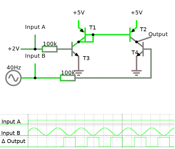
So I came up with a new, improved design which includes hefty resistors which protect the current mirror transistors.
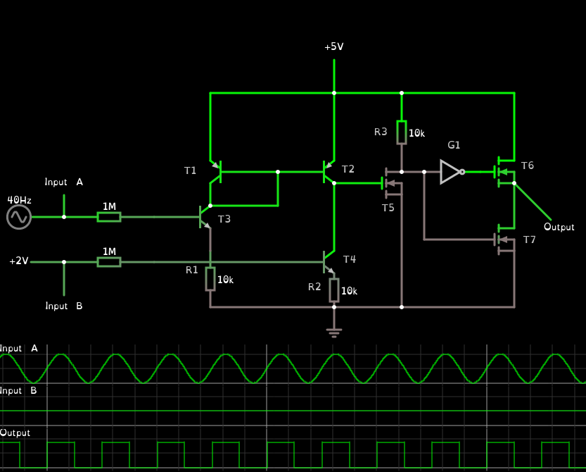
The new circuit has a noticeably higher complexity than the previous one, but there are good reasons for it. The first difference with the old circuit is the large resistors R1 and R2 at the emitters of T3 and T4. They protect T1,T2,T3 and T4 from large currents and add a baseline resistance of 10KΩ into the current mirror, so that manufacturing tolerances in transistor resistance don’t matter any more. The downside is that the intermediate output voltage at T2’s emitter is not a square signal any more; its signal form and amplitude depends a lot on the combined load of input A and input B.
The problem is solved with T5, which is a MOSFET and thus doesn’t place any load on the current mirror. However it acts a bit like an amplifier in overdrive, converting the wobbly signal at T2’s emitter into a square-like signal which is what we want.
We could have stopped the design there, but since I want to drive a decent load with the output signal I added T6 and T7 which generate a strong 0…3,5V signal at the Output pin.
Special thanks to the amazing Circuitjs project which simulates all my electronics projects.
As always you can try the circuit out here.
