Readers of this blog know that I’m fascinated by everything around switched amplifiers. The core piece of every switched amplifier is a voltage comparator. Today I’ll write about a comparator design based on an oscillator.
The simplest voltage comparator compares two input voltages A and B and outputs a high voltage is A > B and a low voltage if B < A. It’s behaviour for A = B is undefined.
Unfortunately, building the “simplest” voltage comparator is not a simple circuit, especially when operational stability is important. The simplest voltage comparator which deviates from the strict definition but is still somewhat useful is depicted in the circuit below:
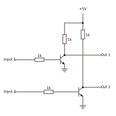
This circuit (the resistor values and voltages are arbitrary and should be ignored) outputs the voltage difference of input2 – input1 (multiplied by some arbitrary factor) as a voltage difference Out2 – Out1 (yes, it’s inverse). The comparison result is distributed over two wires, Out1 and Out2, and you need both to make sense of the comparison which is rather uncomfortable since all voltages are measured against ground.
The action plan is: compute the voltage difference between the two inputs (here “Input” and “Reference”), drive an oscillator on that voltage difference, isolate the alternating voltage part so that it can be measured against ground, detect when the oscillator is running and finally output a high voltage value when the oscillator is running.

Q1 and Q2 make up the simple voltage comparator discussed earlier. The voltage difference between their collectors acts like a voltage source which drives the multivibrator made of Q3 and Q4. As long as the voltage difference is “large enough” (for an arbitrary definition of size) the multivibrator will oscillate. Capacitor values should be low to allow for prompt oscillation start.
Q5 is a buffer meant to isolate the oscillator from the amplification stage. This isolation is important, because otherwise the oscillator loses sensitivity and might take longer to start oscillation. Q6 amplifies the oscillation signal and feeds it over a wave rectifier (those diodes) to a capacitor with a parallel load which smoothens out the oscillation signal to a “on” or “off” signal.
The Schmitt-trigger (SMT1) triggers once the voltage on wave rectifier is high enough. Proper calibration of SMT1 is important; a too low threshold value will cause misfiring and a too high threshold value might lead to delayed triggering.
As always, if you want to play with the circuit, I recommend the awesome circuitjs simulator at lushprojects.
