Many old AM receiver circuits use positive feedback (routing some of the already amplified output signal back into the amplifier’s input) for more gain. These circuits (eg. the reflex receiver [REF]) are fascinating designs which, although not overly complex, aren’t easily understood. Starting with an existing circuit design, I tried to isolate the feedback loop from everything else that’s going on (carrier tuning, AM demodulation, envelope detection etc.) and ended up with this simple design. As always, the simulated circuits are here [CIR] (updated 2026-01-03).
Operating principle
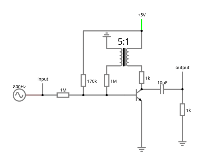
The circuit is basically a common emitter configuration with a transformer feeding back the amplified signal into the base. The transformer’s ratio is > 1, which boosts the signal at the transistor base. And that is all there is to say.
BOM
The input is an arbitrary signal in the -5V … +5V -2V … +5V range. The input resistor of 1M is there just to demonstrate gain; adjust according to the input signal strength. The 170KΩ and 1MΩ resistors are there to bias the transistor – adjust according to the transistor used. The transistor in this circuit is whichever standard NPN BJT Falstad uses. The 1KΩ collector resistor limits current through the transistor. The transformer is at 200mH with a 5:1 ratio (more windings on the collector side, fewer on the base side). The output capacitor and resistor are just there to simulate a load and are not critical. The circuit operates at 5V DC.
Remarks
As always, I didn’t built and test this circuit, it never left the simulator. The circuit seems to behave like a high-pass filter; it doesn’t like low frequencies, which is surprising considering the impedance and lack of capacitance. I don’t know the answer to that (yet). Getting the bias resistors at the base right is somewhat tricky; if they’re wrong, feedback doesn’t do anything. I played around with the bias resistors for hours, it wouldn’t make a difference whether the transformer was connected or not, the feedback wasn’t noticeable until I randomly got the bias divider right and feedback kicked in. The transformer ratio is also somewhat important: too low and feedback isn’t noticeable (duh), too high and it overshoots. That’s especially annoying since, as noted, the amplifier is more sensitive to higher frequencies, so one should test the entire (intended) frequency range to make sure there’s no clipping. In my experiments I didn’t find the transformer impedance to be critical, the simulation worked over a wide range of values. [2025.12.25] Without an output load, the simulator crashes with a convergence failure.
[2025.12.29] Gain can be much improved by matching the load; eg. in the concrete circuit, reducing the capacitor to 200nF almost doubles the amplitude.
Gain
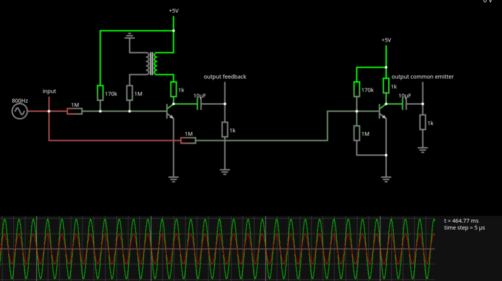
How much gain does this modest effort buy? In order to find out, I compared the amplifier’s output signal with that of the respective common emitter circuit at the same output load. A 800Hz input signal is amplified twice as much by the feedback amplifier than it’s amplified by the common emitter amplifier.
Common base variation
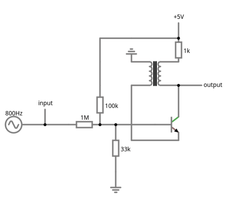
[2025.12.25] An interesting variation is the common base [CB] where the collector current feeds back into the base-emitter current. I found that this variation is more stable and forgiving to sub-optimal parameter settings. Otherwise, the same remarks as with the common emitter circuit apply.
Resources
[REF] Reflex receiver
https://en.wikipedia.org/wiki/Reflex_receiver
[CIR] Feedback amplifier circuit
Simulated circuit
[CB] Transistor common base configuration
https://blog.georgovassilis.com/2021/03/06/transistor-common-base-configuration-a-hidden-champion/
