There is a Mandarin translation of this post.
This is just going to be a quick one. Double push-pull amplifier with cross over compensation explained a high-power amplifier circuit which creates a balance point and corrects for cross over. A much simpler version of the circuit depends on two equal voltage sources creating that 0V balance point, so it used a single push-pull pair instead of two. Also, because we don’t need the 180° inverted signal any more, a single differential amplifier is enough to correct for cross over. Note that while the circuit amplifies power (by amplifying current) it does not amplify voltage: a 2V input signal will lead to a 2V output signal.
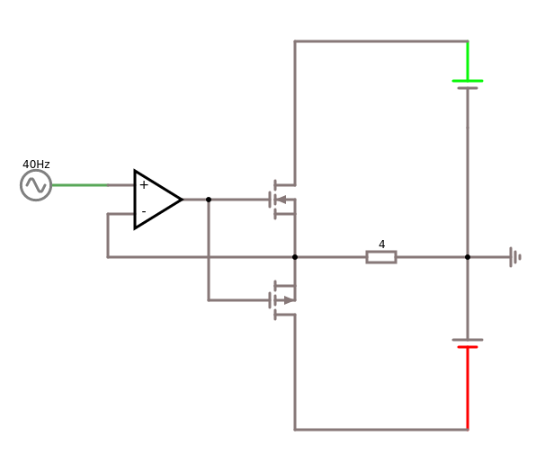
A few short notes about the circuit diagram: 40Hz AC is an arbitrary input signal, but it should be balanced around 0V – an unbalanced signal (eg. if it spends more time on the + side of the amplitude than on the – side) would lead to a net DC current through the PA transistors and the load which might overload some parts of the circuit or, at least, require more cooling.
The 4Ω resistor is a placeholder for an arbitrary output load like a speaker or transformer coil – the reason why one would build this amplifier in the first place.
The two batteries must be of equal voltage, internal resistance and power so that even under load they accurately balance out at 0V (ground). Their voltage depends on the rest of the circuit, I think 5-12V should be ok for most applications.
The transistors are a PNP and NPN MOSFET pair that should be spec’d largely enough to handle the planned load. Their threshold voltage shouldn’t be too high, but is – in theory – indifferent because the opamp takes care of any cross over distortion.
The differential amplifier serves several purposes:
1. it decouples the input signal from the amplifier through its high input impedance.
2. it amplifies the input signal
3. it compensates for cross over distortion in the output by comparing the input signal to the output signal
4. it can compensate, within limits, for an unbalanced voltage source
Since the circuit does not amplify voltage the opamp nominal output signal amplitude should be large enough to drive the MOSFET transistor pair. Especially for high frequencies, the opamp serves as a MOSFET driver by providing a large enough output signal to compensate for MOSFET gate capacitance.
